Ultrasonic Testing of anchor bolts
In Highway Signs and Traffic Signals
By David Reid, CWI
Last week I provided a review of ultrasonic testing (UT) for bolts and pins. In this article, I will build upon the first article with an in-depth review of the ultrasonic testing of steel anchor bolts on highway signs and traffic signals. My experience working with three different state departments of transportation informs this article based on my background and research working with cantilever signs.
Background
Before going in-depth on ultrasonic inspection for cracked anchor bolts, it helps to understand why these inspections are necessary.
One very windy day, I witnessed two different four-bolt cantilever signs rocking back and forth. Both of these signs were in the downtown area of a large city with high volumes of traffic driving past them. My immediate thought was, this is an accident waiting to happen. If it wasn’t so windy, I wouldn’t have given much thought to the nuts not being in firm contact with the base plate.
Bolt failure in four-bolt cantilever signs has been documented. High wind loads were a primary reason why these anchor bolts failed (Garlich and Thorkildsen 2005, p. 7).
Ultrasonic testing (UT) can be used to inspect these types of signs. In some states, the use of UT has been expanded to the inspection of all highway signs and traffic signals.
Visual Inspection Prior to Ultrasonic Inspection
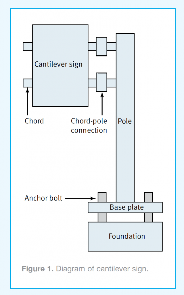
A diagram of the typical four-bolt cantilever sign is shown in Figure 1. Top and bottom nuts that are not in firm contact with the base plate and loose bolts at the chord-pole connection are a couple of reasons why an anchor bolt could crack. These can be checked by hitting the nuts and washers with a hammer to see if they move. If you have ever, on a very windy day, stood next to a highway sign with nuts that are not in firm contact with the base plate, you will see the sign rocking back and forth.
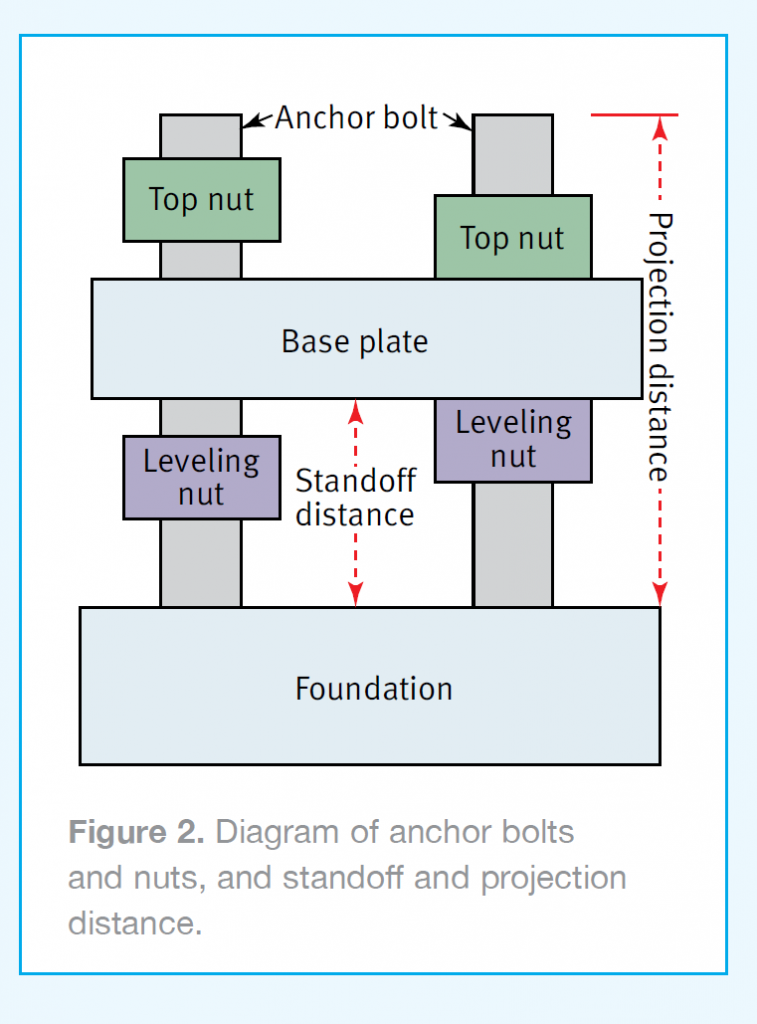
Another reason why anchor bolts crack could be the stress put on them if the standoff distance between the top of the foundation and the bottom of the base plate is more than 2× the bolt diameter, as demonstrated in Figure 2 (Garlich and Thorkildsen 2005, p. 32).
NDT glossary
SHEAR WAVE TESTING
Entries adapted from the nondestructive Testing Handbook, third edition: Vol. 7, Ultrasonic Testing. Columbus, OH: American Society for Nondestructive Testing (2007).
Angle beam testing: Technique of
ultrasonic testing in which transmission of ultrasound is at an acute angle to the entry surface.
Angle beam transducer: Transducer that transmits or receives ultrasonic energy at an acute angle to the surface. This may be done to achieve special effects such as setting up transverse or surface waves by mode conversion at an interface.
Transverse wave: Type of wave in which the particle motion is perpendicular to the direction of propagation. Also called shear wave.
Snell’s Law: Physical law that defines the relationship between the angle of incidence and the angle of refraction.
Range: Maximum ultrasonic path length that is displayed.
Pitch-catch technique: Ultrasonic test technique that uses two transducers, one transmitting and the other receiving on the same or opposite surface. Also called double-crystal technique or two-transducer technique.
Wedge: Device used to direct ultrasonic energy into a test object at an acute angle.
Lamb wave: Type of ultrasonic wave propagation in which the wave is guided between two parallel surfaces of the test object. Mode and velocity depend on the
product of the test frequency and the thickness. Plate wave.
A-scan: One-dimensional display of ultrasonic signal amplitude as function of time or depth in test object.
B-scan: Data presentation technique typically applied to pulse-echo techniques. It produces a 2D view of a cross-sectional plane through the test object. The horizontal sweep is proportional to the distance along the test object and the vertical sweep is proportional to depth, showing the front and back surfaces and discontinuities between.
C-scan: Presentation technique applied to acoustic data and displaying an image of 2D test object with scaled grays or colors
representing the ultrasonic signals. The amplitude represented in each pixel may be a pulse-echo, through-transmission, or pitch catch value calculated from each
A-scan datum.
Ultrasonic Inspection Procedure
Each state department of transportation should have a specific ultrasonic inspection procedure, not just a reference to ASTM E114. A common problem is that these inspection procedures and reports do not have all the information that both the technician and engineer need to know. The result could be misleading or cause incomplete inspection results, and in a worst-case scenario, a cracked anchor bolt
could be missed.
As an example, a procedure that calls for a 0°, 5 MHz, 0.5 in. (12.7 mm) diameter transducer might be limited to a 1 in. (25.4 mm) diameter and larger anchor bolts. Bolts smaller than 1 in. (25.4 mm) may require a different transducer and reference standard. The following sections
illustrate examples of other things the inspection procedure might not tell a practitioner.
Transducer for the Inspection
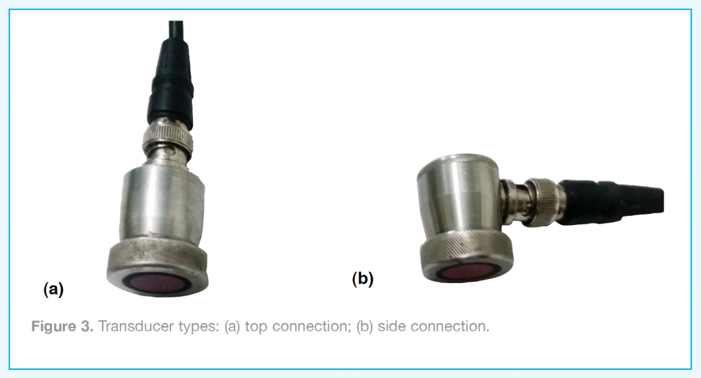
Typically, the transducer required is 0°, 5 MHz, and 0.5 in. (12.7 mm) in
diameter, but the procedure might not specify that a cable connection on the top will be needed. A transducer with the cable connection on the side might not be able to properly sit on top of the bolt being tested if the nut has 75% or less thread engagement (Figure 3).
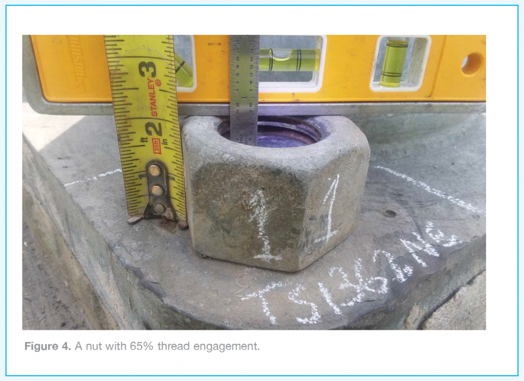
Full thread engagement is when the end of the bolt is even with or above the outer face of the nut. The percentage of thread engagement should also be reported. This can be solved with basic math. As an
example, if a top nut is 2 in. (50.8 mm) tall but the anchor bolt is 0.5 in. (12.7 mm) below the top surface of the nut, that equates to 1.5 in. (38.1 mm), or 75% of the threads engaged (Figure 4). Typically, a top nut with 75% or more thread engagement is acceptable (Garlich and Thorkildsen 2005, p. 80).
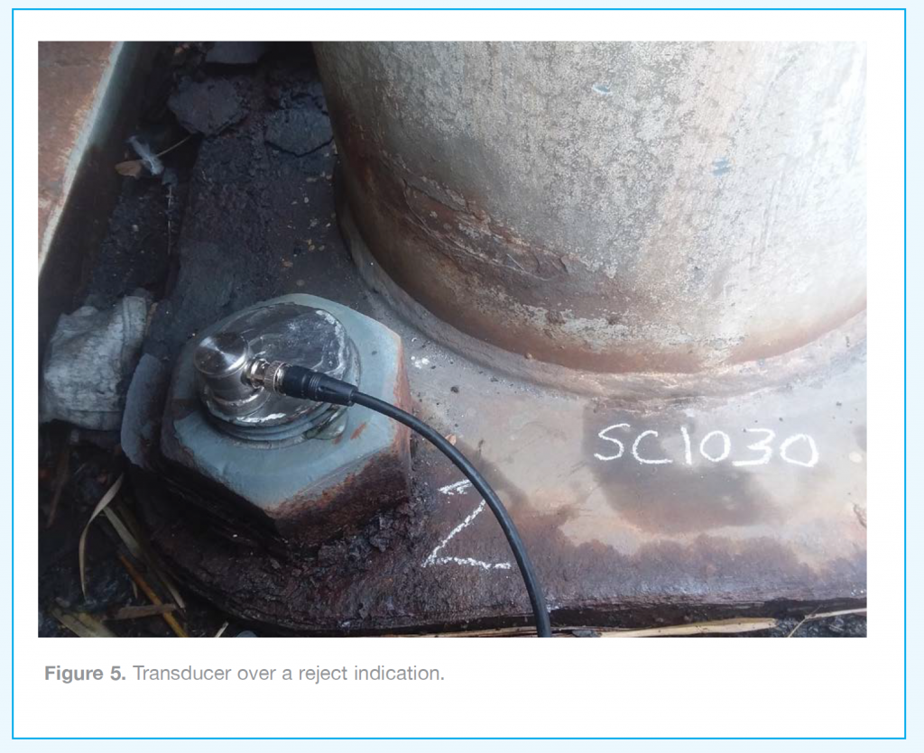
For nuts with less than full thread engagement, it should be noted on the inspection report that the ultrasonic scanning area will be reduced because the transducer cannot get as close to the edge as it could in the case of full thread engagement (Figure 5).
Preparation for Inspection
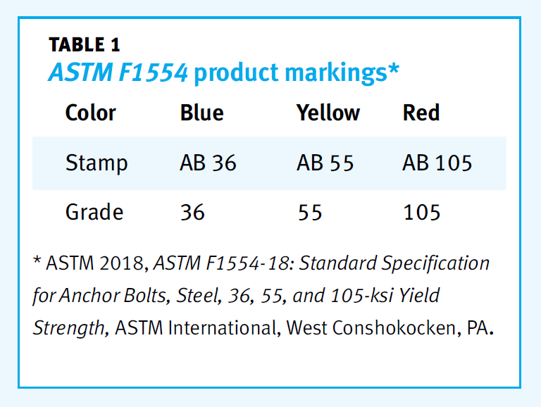
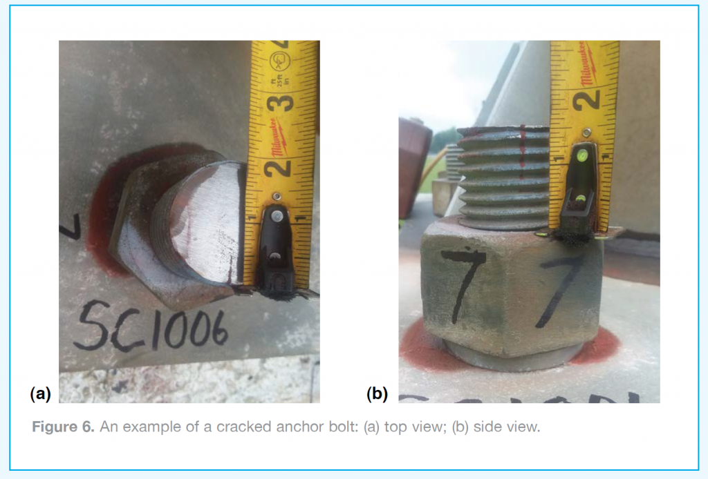
Preparation of the anchor bolts for the inspection requires the top surface of the bolt to be ground smooth, flat, and level. That would require having an electrical generator on site and two different types of grinders. The generator would need to have enough running wattage to run the grinders. For bolts where the nuts have full thread engagement, an angle grinder is needed. But if the nuts have less than full thread engagement, a technician would need a rotary tool grinder with a small-diameter grinding stone. If the top surface of the bolt has not already been ground smooth, it is recommended that the product marking as defined by ASTM F1554 be noted on the report, as seen in Table 1 (ASTM 2018, paragraphs 18 and S3). While grinding, look for cracks on the top of the bolt (Figure 6).
In addition to the grinding disks and small-diameter grinding stones, the technician will also need some cutting wheels. On some structures, the anchor bolt nuts have covers on top. If the erection crew sets the bolts too high, they will need to cut off the top of the bolt so they can put covers on. Often when this happens, the cut that is made is not a straight, smooth, level cut that is ready for an ultrasonic inspection. It would need to be cut again to get it right.
If the technician finds a nut welded to the bolt or base plate, it should be reported. Anchor bolt nuts are supposed to be a heavy hex type that has been heat-treated “hard.” Regular hex nuts are “soft” (not
heat-treated). The height of a heavy hex nut is equal to the bolt diameter. The height of a regular hex nut is less than the bolt diameter. It is often a problem when “soft” regular hex nuts are tightened using a “turn
of the nut method,” the threads strip out before the bolt reaches the required pretension (Garlich and Thorkildsen 2005, pp. 33, 35; SSTC 2016, pp. 111, 132). Welding the nut to the bolt may look sufficient, but in reality, the bolt has not been properly pre-tensioned.
Reference Standard for the Inspection
Most of the procedures require a special reference standard made from a 10 in. (254 mm) long section of an anchor bolt. It should state the minimum diameter of the reference standard. If a technician does not already have one, they may have to make one. If the technician’s state department of transportation does not have a spare bolt, a local concrete precast fabrication shop may have one. The procedure may call for a reference standard with a 0.25 in. (6.35 mm) deep saw cut in the threaded portion of the bolt, 3 in. (76.2 mm) from the end. This allows the technician to standardize the distance for 3 in. (76.2 mm), 7 in. (177.8 mm), and 10 in.(254 mm) before establishing the sensitivity reference level as detailed by the inspection procedure.
Range Setting on the Ultrasonic Unit
When conducting the actual inspection, the procedure may specify a 10 in. (254 mm) range setting on the ultrasonic equipment. A common problem is that a 10 in. (254 mm) range setting is not adequate in all situations. Cracks in anchor bolts can occur about 0.125 in. (3.175 mm) below the top of the base plate, but typically occur about 0.75 in. (19.05 mm) below the top of the foundation the bolt is embedded in. With this in mind, the range setting should be equal to the projection distance plus 2 in. (50.8 mm) (Figure 2). As a result, a 15 in. (381 mm) range setting might be required.
Ultrasonic Inspection for Cracks
The technician should scan the top surface of the bolt as detailed in the inspection procedure. Indications from cracks are typically tall, sharp, and tight due to the large difference in the acoustic impedance across the reflection interface between the base metal and the crack, which is essentially air. The indications should be evaluated as required by the procedure.
Indications from corrosion are typically short, fat, and sloppy due to the small difference in the acoustic impedance across the reflection interface between the base metal and the corrosion. A common problem is that most procedures do not address how to evaluate or report an indication caused by corrosion. It is recommended that a visual inspection of the bolt be done between the top of the foundation and the bottom of the base plate. Further evaluation of the indication would require the cognizant NDT Level III to
provide written guidance.
Measuring the Length of Anchor Bolts
Reporting requirements may include noting the length. What the inspection procedure might not tell you is there are two basic types of anchor bolts: straight end and hook end (figure 1 in ASTM 2018), and there are differences in how they are measured. The length can be rounded up or down to the nearest inch to get the
approximate length. It is only when the technician finds a reject indication that accuracy to the nearest thousandth of an inch would be required. (As a note, the author sets the gate trigger on “flank” instead of “peak” since measuring the distance to the reject indication is the primary purpose of this inspection.)
Measuring the length requires a longer range setting than what is used for the crack inspection. In the field, anchor bolt lengths can range from 25 in. (635 mm) to 140 in. (3556 mm). With this in mind, a 150 in. (3810 mm) range setting is a good starting point. For a straight end bolt, a gain setting of approximately 18 dB above the sensitivity reference level is adequate to measure the length. For a hook end bolt, a higher gain setting (approximately 36 dB above the sensitivity reference level) might be required to measure the length.
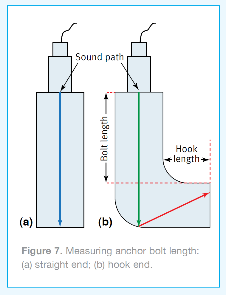
Measuring the length of a straight end bolt is straightforward and simple. It is similar to a crack; the left side of the indication is perpendicular, but it might be wider along the horizontal baseline (see the blue sound path in Figure 7). Measuring the length of a hook end bolt is subjective. There may be one or two indications, or nothing. Indications from a hook end are similar in appearance to corrosion: short, fat, and sloppy. If there is only one indication, it could be the length of the bolt plus the hook length (see the red sound path in (figure 7). If there is a second indication located to the left of the first indication, it could be from the radius of the bend that forms the hook (see the green sound path in Figure 7). And then sometimes the soundwaves bounce off into left field, and the technician gets nothing. If the policy is to record the length of hook end anchor bolts, it should be understood that the measurements might be the length of the bolt plus the length of the hook.
After the Inspection
Once the inspection is complete, it is recommended that the technician clean the bolt tops and apply a cold
galvanizing compound. It is sold as a spray at most hardware stores.
Conclusion
If your state department of transportation refers to only ASTM E114 or has an ultrasonic inspection procedure that does not address some of the issues mentioned here, it is recommended that the NDT
technician ask the cognizant NDT Level III or structural engineer to review this article. Approval in writing should be received before incorporating any of these recommendations into the way one performs these types of inspections for their local jurisdiction.
David J. Reid, CWI is an ICC Special Inspector in F&R’s Chesapeake operations center. He is a Level II Magnetic, Particle and Ultrasonic Testing Technician and his nearly 30 year career in nondestructive testing and metals services has spanned projects from aviation and transportation to industrial, power and commercial construction.
REFERENCES
ASTM, 2018, ASTM F1554-18: Standard Specification for Anchor Bolts, Steel, 36, 55, and 105-ksi Yield Strength, ASTM International, West Conshokocken, PA, Figure 1, Paragraphs 18 and S3.
Garlich, Michael J., and Eric T. Thorkildsen, 2005, FHWA NHI 05-036: Guidelines for the Installation, Inspection, Maintenance and Repair of Structural Supports for Highway Signs, Luminaires, and Traffic Signals, Federal Highway Administration, Washington, DC, pp. 1, 6, 7, 32, 33, 35, and 80.
SSTC, 2016, Structural Bolting Handbook 2016, Steel Structures Technology Center Inc., Howell, MI, pp. 111 and 132.
